As with many of my projects, I have to create a separate project to build a tool for it. In this case, I needed to make a Lithium Ion battery pack. Rather than solder, I decided to make a spot welder to put the battery pack together.
Lithium Ion batteries are heat sensitive. They can be soldered together if one is careful in not applying to much heat for an extended period of time. However, a much safer method is to use a spot welder to weld the batteries together. To me, this was a great reason to embark on yet another project! Besides, you never know when you will need a spot welder.
This spot welder basically uses a car or lawnmower battery to to provide the current necessary to do the spot welds. The amount of current that will be applied to the weld is fairly high. I expect in excess of 200 amps. To accommodate this we’ll be using a starter solenoid to pass the current. We’ll control the amount of time current is applied with a control board and a trigger. I’ll also be making a welding pen to complete the spot welder.
Building the Spot Welder
Here’s a quick list of the components I used to build the spot welder.
Starter Solenoid
Timing control Circuit
3 mm copper rods (for welding pen)
red and Black 8 Gauge Primary wire
Terminal Lugs (8 gauge)
Bell wire
Momentary Switch
Making a Base for the Spot Welder
I started this build by making a base out of some pine boards I had laying around. Basically, I made an L shape put of two pieces. One piece being the base and the other piece being upright. The upright piece would be the one that I attached the components too. The bottom piece is just there for stability.
Mounting the Components
Next, I attached the Solenoid to the upright wood on the base. I drilled two holes and used bolts and nuts to attached it. I also added the timing control circuit board at this time. This board comes with two plastic standoffs to lift the board off of whatever surface it is mounted too. I installed the mounts on the control board and then mounted it with hot glue.
Solenoid mounted to spot welder
Control Board Mounted on Spot Welder
Before going any further with wiring, I needed to make two things. One was a trigger with a momentary switch. The other is a welding pen. Both of these were fairly easy to make and I’ll give you a quick overview here.
Making a Trigger
To make the trigger, I used a momentary SPST switch.First I made sure I had enough bell wire so that I had some slack to move the switch around when using the welder, I ended up using about two feet of wire. I soldered the the red and black Bell wires (about 20 Gauge) to the switch.
Next, I inserted the wire through a 6″ long piece of 3/4″ pvc. Luckily, the edge of the switch was wide enough to sit on the edge of the PVC. After that, I slid shrink tubing over the entire assembly, making sure that the edge of the shrink tubing overlapped the edge of the switch. While hitting the tubing with the heat gun, I made sure that the tubing curled around the edge of the switch to hold it in place.
Making the Welding Pen
The welding pen was a bit more complex to build. I used two 3mm copper rods as the electrodes. The first challenge was to devise a method to hold them in place while welding. The second was to attach them to the 8 gauge primary wire. I initially tried soldering then but that turned into a huge mess. I ended up using copper crimp connectors. These slid right over the wire and copper rod and held everything firmly together when crimped.
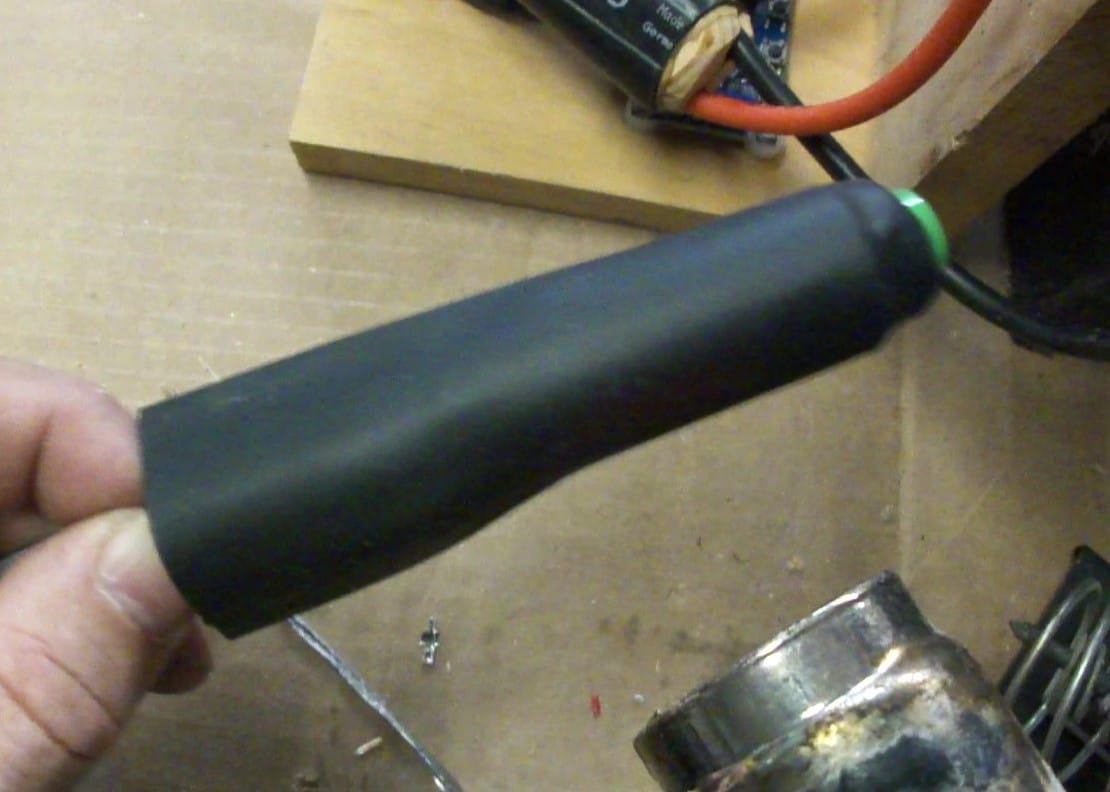
Building a Handle for the Spot Welder Pen
The handle needed to be sturdy enough to hold the two copper rods in place as well as comfortable to hold. I ended up using an old wooden stair-step from an attic pull down ladder. There were grooves in the stair-step that the rods could lay in. I ended up cutting two pieces that I would screw together with the grooves facing each other. The idea being that the copper rods would be held in place by the grooves.
I used a Dremel tool to carve out areas at one end to make room for the 8 gauge wire. I had to do a bit of carving so that the copper rods would lay in the groove and also have enough room for the wire. Once I had this done, I used small screws to clamp the two wood pieces in place. As a final step, I enclose the handle in a piece of heavy duty shrink wrap.
Wiring up the Homemade Spot Welder
The 8 Gauge cables
The 8 Gauge primary wire serves two purposes.The first, and arguably the most important, is to carry the current from the battery through the solenoid to the welding pen. The second, and as important, is to connect to the battery. I went with 8 gauge cables because of the amount of current they would be handling. Even 8 gauge technically is not large enough, but with the small amount of time they would be carrying current, I figured they would be fine. In case you’re wondering, they were.
The Welding pen
I purchased cable terminal lugs specifically for 8 gauge wire. The particular ones I got came with heavy duty shrink wrap, one red and one black. The shrink wrap also had a glue inside so that as you shrunk it, it also melted the glue and put a protective layer inside the shrink wrap.
I cut off about 12″ of both red and black wire and set those aside for now. Next, I crimped two terminal lugs on the end of the red and black wires coming from the welding pen I made. The red wire terminal lug is connected to one side of the solenoid. The Black wire terminal lug is connected to the bolt holding the solenoid to the stand.
Connections to the Battery
Using the two wires I had cut and set aside, I made the final connections to the battery. I crimped a terminal lug to one end of the red wire and a large alligator clip to the other. Next, I repeated the same connections to the black wire.
Both of these wires will be used to connect the spot welder to the battery. The red wire is connected to the other side of the solenoid using the terminal lug side.
The black wire is connected to the bolt on the backside of the stand (Same bolt we connected the black wire from the welding pen).
I did it this way so that it would be easy to connect to a battery. Having the black (negative) side go through the bolt also provides a ground for the solenoid. At this point, I also ran a piece of black bell wire between the front ground (Bolt holding the solenoid on) and one of the control lugs on the solenoid (Small connector)
Wiring the Control Module
Wiring in the control module was fairly simple. The key circuits we are worried about here are the output circuit which controls the solenoid, powering the control circuit board and the trigger. Below is a diagram that shows the electrical connections I used to get this to work.
To get power to the control board, I basically ran a wire from the terminal lug on the solenoid (the side connected to the battery) to the control board. From there I tapped into the same connection to feed the trigger and the common side of the output relay on the control board.
I also ran a wire (black) to the ground lug we used earlier to provide a ground to the circuit board. I then tapped this over to the common side of the trigger input. This probably sounds more complicated than it really is, which is why I added the electrical diagram to this article!
Programming the control module
Programming the module proved to be a challenge. The instructions that come with it are a poor translation and make absolutely no sense to me. Well they did, sort of, but I found a great tutorial on how to program this module on YouTube Programming the Control Module. I ended up putting the module in Mode 1.
Mode 1 closes the relay on the control board for a defined amount of time and then opens it. This in turns closes the solenoid for that amount of time. Basically the control board allows you to program exactly how long to close the solenoid and provide welding current.
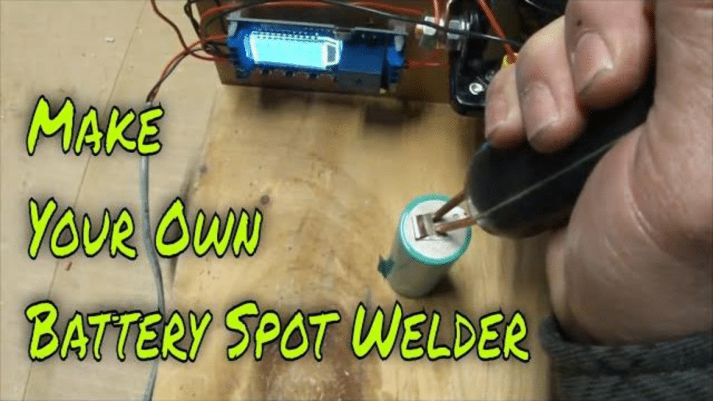
Testing the Spot Welder
I initially set the spot welder for 100ms of time. This looked to be a little hot. It definitely welded a nickel strip on an old Li-Ion battery I had. But it threw a bit of a spark. I played around with the time settings and finally fount that 70 ms seemed to be perfect with this battery.
I think that with different size batteries as a source you would have to play around with the timing on the control board. A 800 cold cranking amp battery will deliver a lot more current than a smaller 200CCA battery. So some adjustments would have to be made. I would definitely recommend testing any setup on scrap metal or batteries first before spot welding a battery pack.