

Preparing the boat console for the Boston Whaler Restoration was an interesting endeavor. I had originally wanted to control the power from the engine remote controller. Instead, I opted to add a push button switch that would power up the console. The reason for this is that I wanted to be able to have power available without energizing the engine. This makes anchoring and using other electronics or lighting possible without having the engine key in the on position.
In addition to the electrical switch panel and Tachometer, I also installed the Sierra Teleflex Q-T Helm. As long as I had the boat console on the bench, it seemed logical to do this at the same time.
Boat Console Components

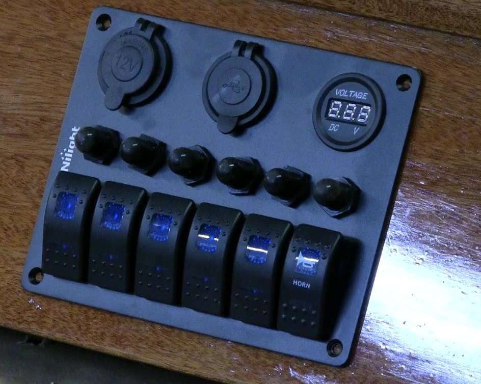
To do this I used a panel I got from Amazon (affiliate link at end of article). I opted for this particular panel because it had integral circuit breakers. Having the integrated circuit breakers saved me from having to install a fuse panel. Additionally, it had a cigarette lighter socket as well as USB power ports. Overall, it is a convenient package.
I did make one modification the switch panel. I added a horn button which is basically a momentary switch. The built in switches are all on or off which really aren’t suited for a horn.
Additionally, I added a Faria Tachometer as well as a few other items to the project. The Faria tach was interesting to put in and wire. I say that because most folks would do all the wiring to the tach from the engine or engine control. I opted for a slightly different approach. I’ll cover that in more detail later.
One different approach I took was to add connectors to every connection between the console and the boat. I used Amphenol ATP connectors. These are made for automotive use and are IP 65 rated so are waterproof. I used these so that if in the future I had to take the console out, I could simply disconnect it via the plugs.
Cut Out The Areas for the Boat Console Components
The first thing I needed to do was to cut out holes in the console for the pane, tachometer and helm. I needed to leave enough room from the edge of the console to accommodate an on/off switch to the panel as well as all the cabling coming in to the console. I decided on mounting the panel six inches from the edge of the console and marked that off.
To make installing the console as easy as possible, I made a template from cardboard. Before I made any cuts, I test fit the switch console in the template. Once I was satisfied that the template was accurate I marked out the area that needed to be cut out. I place the template so that the inside edge lined up with the mark I made earlier. Next, I centered the template top to bottom and carefully outlined where I needed to cut.

Cutting out the Switch Panel Mount
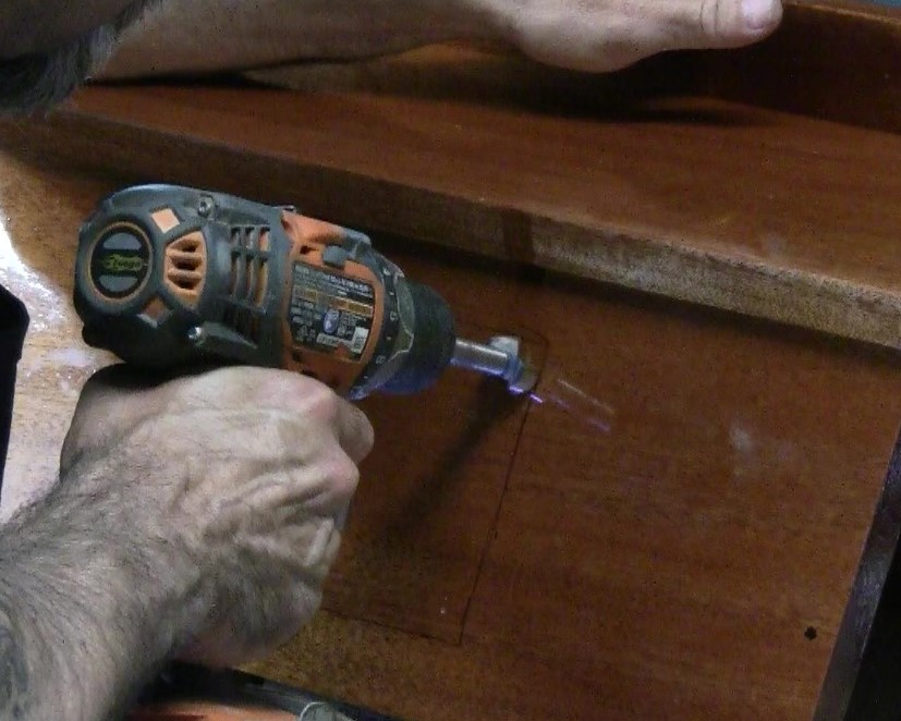
In order to get a nice clean cut, I used two tools. I used a drill with a 7/8” Forstner bit and a multi tool with a universal saw blade. I used the 7/8” bit as it would leave enough of a radius for the corner mounting screws of the panel to grab. The first thing I did was to mark the corners so that the Forstner bit would be centered. I ended up making a mark on each corner 11mm from each edge which perfectly centered the 7/8” Forstner bit. After using a center punch to mark the corners, I drilled out the corners with the Forstner bit.
Next, I used the multi tool to cut out the lines between the holes I had just drilled. After that, I test fitted the panel and it fit perfectly. A quick note on cutting out the hole for the panel. I used a multi tool but a jigsaw would work just as well. The reason I used the multi too was that there would not be contact with the varnished surface. If you use a jig saw, mask off the area surrounding it with masking tape. This should be enough to keep the bottom plate on the saw from marring the surface.
Cutting the Hole for the Tachometer

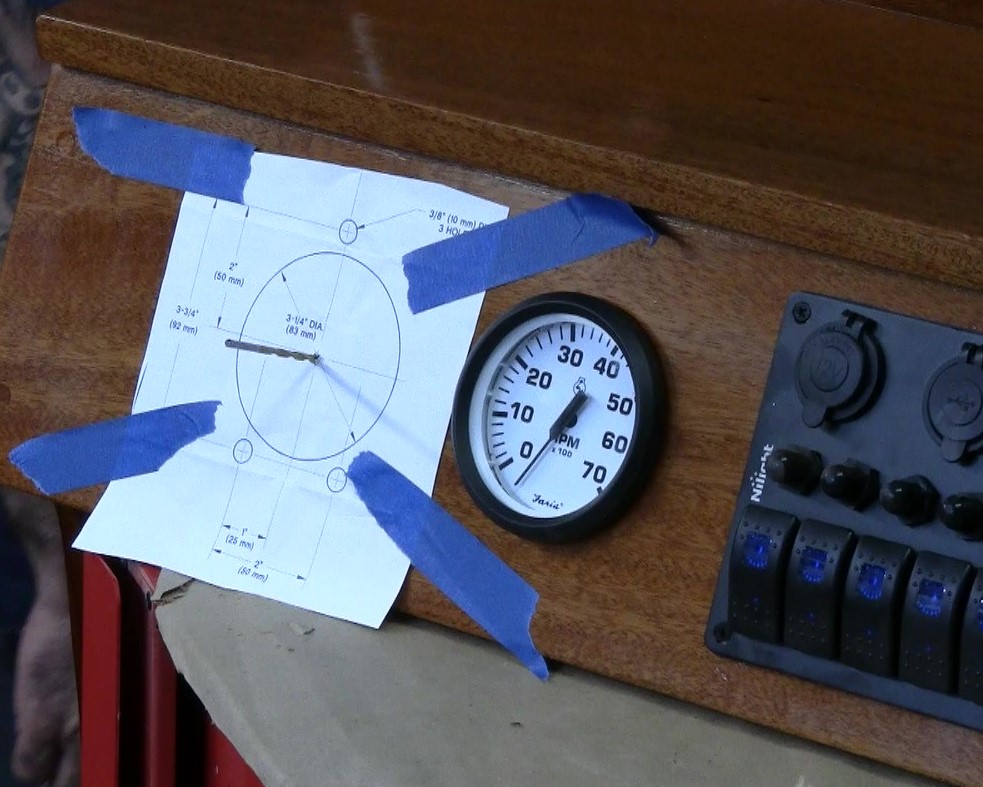
The Faria Tachometer calls for a 3-3/8” hole. I searched for a hole saw that size and didn’t find anything that was affordable for a one time use. I ended up buying an 85mm hole saw. This is a tad small but my plan is to drill it out, and use a drum sander to open it up some. I did make a cardboard template with the hole saw and the hole appeared to be just large enough to fit the tachometer.
To mark the spot I would be drilling, I measured 3-1/2” to the left of the edge of the switch panel and 3-1/2” up from the bottom. This would center the tachometer top to bottom and leave enough room to the left of it to eventually mount the steering system.
When drilling the hole for the tachometer, I first drilled from the outside and then drilled from the inside. This ensured that I would have a nice clean edge on both sides of the console. Once I finished drilling the holes I test fit the tachometer. As luck would have it, it fit perfectly so I didn’t have to use the drum sander to open it up more.
Cutting out the Hole for the Teleflex Helm
The Teleflex helm has a fairly large offset towards port. The console on this whaler is a bit tight, so I need to make sure that when I drill the opening, that the helm will fit in there. To do that I measured 7 inched from the port side of the console and 3.5″ from the bottom. 3.5″ exactly centers it top to bottom.
After marking the spot I needed to drill, I drilled a pilot hole with 1/8″ drill bit. Before drilling anymore holes, I need to mark off the mounting holes for the helm bracket. I did this with the template supplied with the Teleflex kit. I centered the Template using the same drill bit I used for the pilot hole, taped the template in place and then center punched the mounting holes. Next, I simply drilled out pilot hole with the 1/8″ bit and followed up by drilling the mounting hole with a 3/8″ bit.
Sealing the bare wood
One thing I wanted to do before mounting anything was to seal the wood. I used the TotalBoat 5:1 epoxy I’ve been using for the rest of the restoration to do this. Before doing that though, I masked off the front of the panel to protect it from any errant drips. Getting the epoxy on was pretty simple, I used a small chip brush to dab the epoxy into the bare wood.
Mounting the Boat Console Components
Mounting the Switch Panel
The next step was to mount Switch Panel and the tachometer on the boat console. Mounting the switch panel was a simple effort. First, I slid the panel into place and marked where the screw holes would go. Next, I drilled out the screw holes with a fine bit. Finally, I placed the gasket that came with it on the back of the panel and slid the entire assembly into place. The last thing I did was secure it in place with four screws.
Mounting the Faria Tachometer on the Boat Console
The next step was mounting the tachometer. This involved simply placing it in the hole we had drilled earlier. There is a back plate that comes with Tachometer. The backplate holds the tach in place. With their design, the screw lugs for attaching the tachometer wiring go through the backplate. The nuts that are used to secure the wiring actually push the backplate up against the back of the console, effectively securing it in place.
Mounting the Teleflex Helm
The last step before calling this phase of the restoration complete was to mount the SeaSense Teleflex helm. The instructions are pretty explicit and easy to follow. You’ll want to start by drilling the mounting hole with a hole saw. The instructions call for a 3-1/4″ hole. I used the 85mm hole saw as that was close enough.
Drilling the Holes for the Helm
Before you drill a hole in your console, you’ll want to make sure there’s enough clearance for the unit itself as well routing the Teleflex cables. SeaSense recommends that cables be routed to the starboard side and that a minimum of 12 inches of clearance be provided. This allows for minimum acceptable radius of 8″ to bend the steering cables.
After you establish the location, I recommend using the template they provide in the kit to drill your holes. I taped the template on to the panel with the center exactly where I wanted to position the hole. One I had the template in place I drilled three 3/8″ holes at the points marked on the template. Next I center punched the starting point for the 85mm hole saw and cut out the hole for the helm.


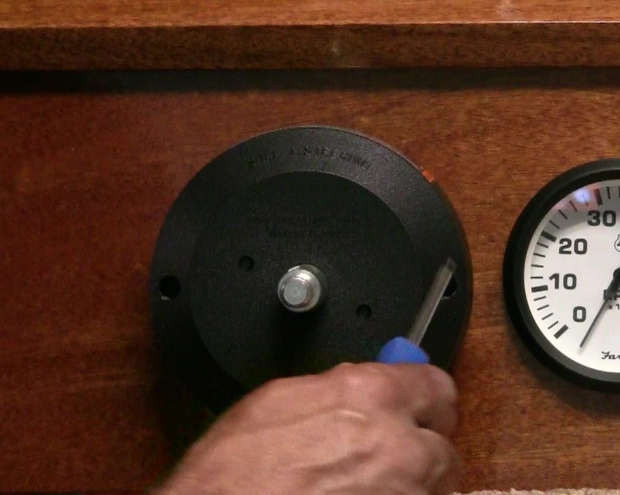
Installing the Helm Mounting Bracket

You’ll want to mount the helm mounting bracket next. The bracket is mounted from the outside, with the deeper portion placed in the 85mm hole. You’ll want to use the bolts supplied with the kit. SeaSense recommends torqueing them to a minimum of 110 inch pounds, not to exceed 145 inch pounds.
Once the mounting bracket is installed, the helm can be installed from the rear.
The mounting bolts will install through the bracket to fasten the helm. These bolts should be tightened to 75 inch pounds, not to exceed 120 inch pounds.

Last but not least is the bezel. This is easily installed by sliding it over the steering column and securing it to the panel with the provided screws!
This completes Boat Console and Helm Prep. I should be posting an article soon on the console wiring for the switches and tachometer. Stay tuned for it!
Make sure to check out the entire Classic Boston Whaler 13 restoration series here 1966 Boston Whaler 13 Restoration. Also, here are a few links to YouTube video related to this article:
Amazon affiliate links to items I used:
