If you love old boats and outboards, you’ll eventually have to replace a fuel pump. OEM replacements can be expensive. The outboard fuel pump I’m rebuilding here has an OEM cost of about $75! Before buying a replacement, you should consider an outboard fuel pump rebuild.
Outboard Fuel Pump Rebuild Kits
You can buy an outboard fuel pump rebuild kit for a lot less than buying a replacement. The Sierra kit for my fuel pump cost around $10. See the link at the end of this article for the rebuild kit I used here. Alternatively, you can also buy an aftermarket fuel pump, Sierra makes reliable fuel pumps and they are reasonably priced. Personally, being a DIY maverick, I prefer to go for the rebuild.
The Outboard Fuel Pump Rebuild
Disassembling the Fuel Pump
Once the cap is off you’ll find that there are two screws holding the body of the pump together. You’ll want to remove these screws. Put some pressure on the body as you remove these screws. There are several springs in the pump that can potentially pop out or push the assembly apart. The rebuild kit has these springs but you may want to take note of where they are located.
Next, Remove the gasket from the top plate. The replacement gasket should fit on it correctly in any orientation. Then, remove the top plate off of the pump body. You may want to hold the sides of the pump body with your fingers when doing this. It is unlikely the pump will fall apart but it’s a good precaution. Take note that there is a small “u” on the part of the plate that faces up.
Disassemble the Fuel Pump Body
Start with the lower plate on the body. This plate is where the diaphragm and diaphragm spring are located. Your fuel pump rebuild kit will contain replacements for all these parts. You can remove the old diaphragm and spring and set them aside in case you lose the spring or spring cap from the rebuild kit.
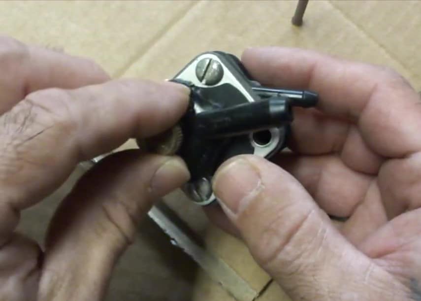
Next you’ll take the output assembly off. It pays to pay close attention to where it was on as the location of the spring underneath it is critical for correct operation. It’s actually not that complicated and I will give you a clear explanation of where the air dome spring is supposed to sit in relationship to the housing when we re-assemble the pump. In this picture, you can see the fuel outlet housing on the right. On the left is the base of the fuel pump with a gasket still on it. Underneath that gasket is where the air-dome spring sits. More on that later.
Cleaning all the Components
Now is a good time to clean all the parts. I use carburetor cleaner in a spray can. In some cases, I had to carefully scrape the old gasket material off. Spraying by itself is not going to completely clean the parts. You may need a small pick of some kind to poke out the crud you’ll find in some of the holes. A few q-tips will come in handy as well.
Reassembling the Fuel Pump
To re-assemble the pump, I poke two nails through a piece of cardboard. The nails will help in keeping everything lined up as you put the pump back together. You can also use the two screws that held the pump together. Or you can even use the screws that mount the pump to the motor. I prefer the nails since they are easy to poke through cardboard.
The first thing you’ll do is place the fuel pump on the nails (or screws). Use the holes that are not threaded. Look at the picture and notice the orientation. You want to make sure that the two tabs on the base are pointing upwards. Everything we do going forward is going to use those two tabs as a reference.
The Fuel Pump Diaphragm
Next, you’ll place the diaphragm on to the base. Use the screws as a guide and seat the diaphragm all the way on to the base. Make sure that at least one of the tabs on the diaphragm line up with a tab on the base. There’s a small cap, called a diaphragm support for the diaphragm spring. That cap rests on the center of the diaphragm and the spring sits on top of it.
This picture shows the diaphragm, the cap and the spring positioned on the base. Note that I oriented the diaphragm so that one tab is oriented with the tab on the left of the base.
Next, you’ll want to place the valve housing on to the spring. The valve housing should be oriented so that the two (tiny) vents are facing downwards. The side facing down has a small recessed cup that the spring fits into.The bottom of the valve housing has two tiny vents. These vents should be pointed downwards. There will also be two tabs on the housing which should be aligned with the two tabs on the base.
After you have the valve housing in place, you’ll want to place the valve housing gasket on it. This has to go on correctly. There are two curved holes in the housing. Match the curved holes on the gasket so they fit exactly over the holes in the valve housing. If you have matched the curved holes in the gasket to those in the housing, all the other holes will match up correctly.
Correctly Positioning the Air Gap Spring
Now comes the tricky part. This is where is a lack of information on how to correctly position the air gap spring. I was lucky enough to find scanned copies of a manual that showed exactly where to position the spring relative to the fuel outlet.
Basically, the spring will sit in one of the two curved cavities. Where it sits is determined by the position of the fuel outlet. The way this works is that the outlet needs access to the area the spring is in. Looking at the fuel outlet housing, you’ll notice that there is a small passage between the outlet and the adjacent cell. The outlet will either have direct access to the spring or access to it via the passage. You’ll also have to take note of the tab on the outlet housing, it should match up with one of the tabs on the base.
Here are a series of pictures showing every possible configuration. The correct spring location is identified in each of them. Notice that the tab on the fuel outlet housing is always lined up with one of the tabs on thetop of the base.
Lower Right Fuel Outlet
Lower Left Fuel Outlet
Upper Right Fuel Outlet
Upper Left Fuel Outlet
Placing the Air-Gap Diaphragm and Spring in Place
Once you have determined where the air-dome spring is going to sit, you’ll want to place the spring in that cavity, the small cap will sit on top of that spring. Once the air-dome spring is in place, you’ll place the diaphgram supplied in the kit over the spring, cap and gasket. Note that the holes in the diaphragm need to line up with the holes in the gasket.
Testing the Air-Gap Spring
Next, you’ll want to place the fuel outlet housing over the diaphragm. Do this carefully so as not to push the spring out of place. Apply light pressure down on the housing to hold everything together. You’ll want to test the spring with a small blunt object. Make sure that you can depress the diaphragm where the spring is at and that it bounces back.
If everything looks right, you are ready for the next step. Hold the sides of the pump and press down so that it does not come apart. Install the cover gasket over the assembly while still holding it together. You don’t have to be concerned about the orientation of this gasket. It will be correct, no matter how you put it on.
Now your ready to put the cover plate on. The cover plate needs to be installed so the the letter “U” is facing away from the pump. There is also a tab on the cover plate. Install the plate so that the tab next to the “U” is lined up with the tab on the fuel outlet housing.
Putting it All Together!
You are now ready to install the screws that will hold it all together. Carefully hold the pump so that none of the sections separate. Install the screws you originally removed in the top and bottom holes. You can screw these in until snug and the assembly will now stay together. You are now ready to install the filter gasket. Place the filter gasket on to the pump, make sure the smaller cutouts are facing the screws. Next, Place the filter cap on to the gasket and screw it in place.
Testing the OMC Fuel Pump
There’s one last final step. Test the fuel pump. Interestingly enough, there’s a simple way to test the fuel pump. You should be able to blow into the fuel intake (filter) and blow through the filter, it may make a small vibrating noise which is normal. If you reverse it and try to blow through the fuel outlet, it should block you and you should not be able to blow through there.
If it does not pass this test, something went wrong in the assembly. Most likely the air cap spring is either in the wrong cavity or is slightly out of place. If it passes this test then you have completed the the outboard fuel pump rebuild. You can now mount the finished OMC fuel pump on your engine and test for leaks!
Here is a link to the copies of the manual that shows how to rebuild one of these pumps. Leroy has greast information on outboards! Leroys Ramblings, rebuilding a Fuel Pump
Below are Links to the rebuild kit I used. I have also included a link to a direct replacement for Evinrude/Johnson 397274, 397839, 391638, 395091, Mallory 9-35350 fuel pumps in case you don’t want to do a rebuild